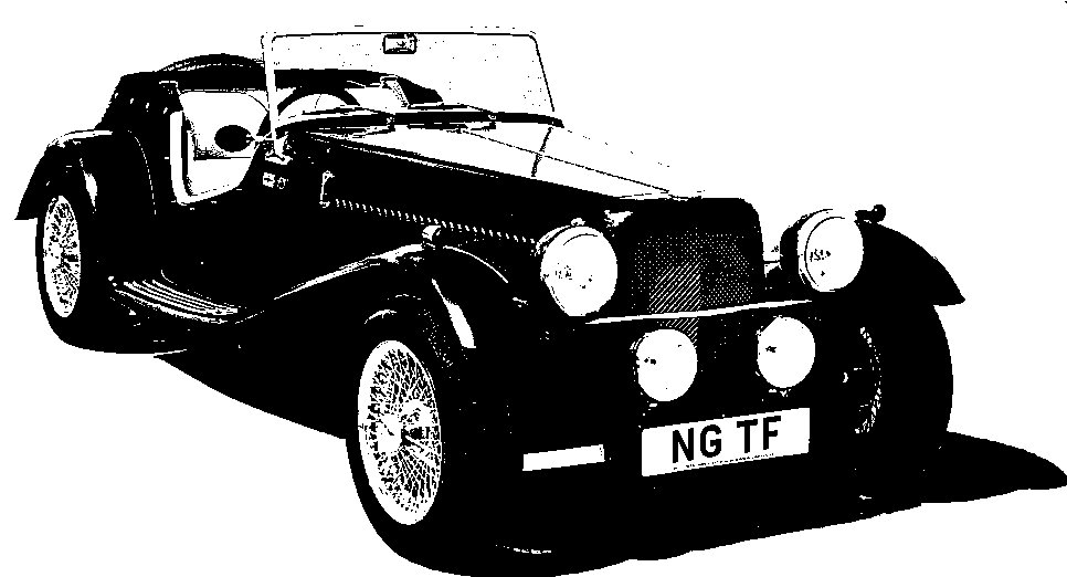
NG Kit Car
17.4 Instruments
I obtained a reconditioned speedometer and tachometer (rev. counter) and new gauges for oil pressure/water temperature and fuel. Also bulb holders for panel and warning lamps.
Speedometer & Tachometer
The speedometer (on the left in photo 1) has electrical connections for main beam warning lamp, panel lamp, voltage regulator (which attaches to the bracket) and an earth wire. There is also, of course, the actual speedometer cable (see below).
The "2 wire" tachometer (on the right in photo 1) has electrical connections for supply, trigger, ignition warning lamp, panel lamp and earth wire. The main 2 connections on the tachometer are a male spade connector for the 12v supply (green from the loom) and a male 5mm bullet connector for the trigger from the coil (white/black from the loom). The white supply wire from the loom is not used.
Note: On the earlier "3 wire" version, the additional bullet connection is for the white supply wire. The supply then passes through the instrument and feeds the coil via the white/black wire.
Oil Pressure/Water Temperature & Fuel Gauges
The combined oil pressure and water temperature gauge (on the left in photo 2) is mechanical so the only electrical connections are for the panel lamp. The water temperature is sensed through a capillary tube, the end of which screws directly into the engine block. The oil pressure is sensed through a small bore copper pipe which connects to the engine block via a flexible pipe.
The fuel gauge (on the right in photo 2) has 2 electrical (male spade) connections plus those for the panel lamp. There is a regulated 12v supply (light green from the loom) and the link to the tank sender unit (green/black from the loom).
Speedometer Cable
The cable was supplied by NG as it is not a standard MGB length. It is actually 2100mm (about 83") but could be a couple of inches shorter. I decided to route it up the right hand side of the footwell to keep it away from the heat of the exhaust. I made two aluminium brackets and used p-clips to hold the cable (see photos).
-
one bracket and p-clip on top of footwell (photo 3)
-
one bracket and p-clip on bottom of footwell (photo 4)
-
one p-clip on gearbox cross member (circled in photo 4)

in central dash

beside steering column

pointer clipped to end of cable

in central dash
Speedometer Calibration
During reassembly after painting, I carried out the pre-calibration process for the speedometer (photo 5) and sent it off to Speedy Cables (Swansea) to calibrate. The method is described in the NG build manual and on the Speedy Cables web site. The SVA examiner later described it's accuracy as being just about ideal (i.e. reading slightly over).