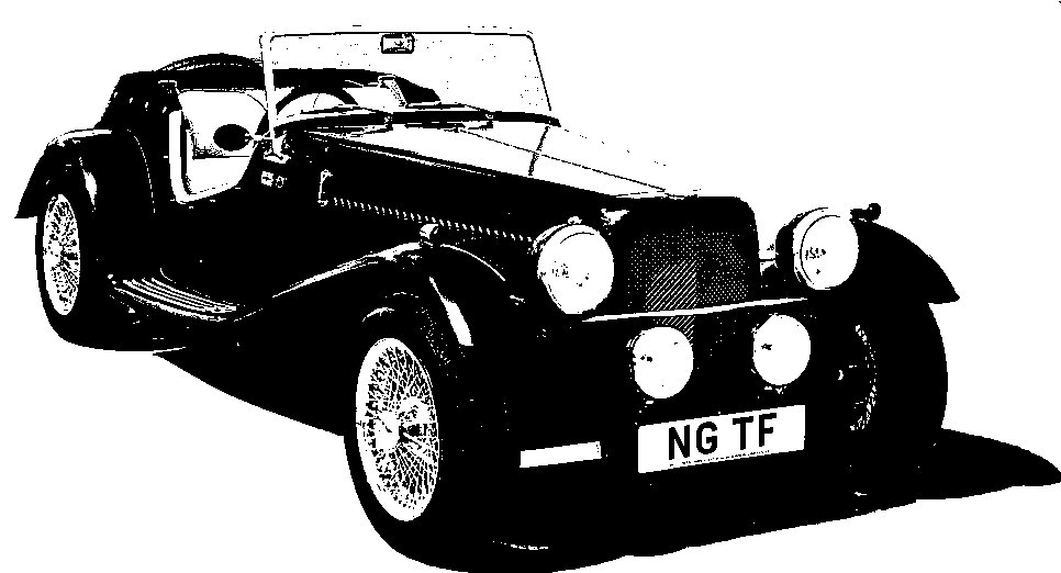
NG Kit Car
15 Bonnet
Bonnet Panels
The aluminium bonnet is made up of 4 panels. There are 2 plain tops which are hinged down the centre and 2 louvred side panels which are fixed (photo 1). All are supplied a little longer than required and need to be trimmed to the correct length and angle. Notice the protective covering on the aluminium.
Top Panels
The top panels are aligned with the centre hinge (see Bonnet Particulars) and the ends measured & trimmed very carefully (back end first). Having first marked a line, I used a jigsaw to cut close to it and then finished off with a file. Standing the panel on its end on a flat surface (e.g. some thick MDF - medium density fibreboard) enabled me to see any imperfections. I also found a 3mm drill bit useful as a way to check the gap between the panels (photo 2).
Once the panel is trimmed to size, it can be clamped to the hinge which is used as a template to drill the holes for the panel fixing screws. I first drilled just one each end and one in the middle and then assembled it with screws to double check before drilling the rest (with the clamps no longer needed). The top panels are also reinforced with a piece of aluminium angle (photo 3) which is shaped at the ends and attached to the nearside bonnet top at the hinge.
Side Panels
Surprisingly the side panels seem to be more awkward. The sides are supplied with the fronts of the bottom edges shaped and folded to clear the crossmember but I found this gave insufficient clearance in my case so I made some adjustments as follows:
-
A piece was cut/ground from the spax bracket (circled in photo 4) to give more clearance to the bonnet side panel.
-
The green lines (photo 5) show where the finished profile is to be. The upper one was needed for the nearside but the lower one seems enough for this offside panel.
I then set about trimming the panel to the correct length. This time I found it easier to trim the front end before the back. A piece must also be cut from the back of each end of the top flange to make room for the bonnet rubbers. Note that the thicker rubber supplied goes around the cowl and the body tub and the thinner self adhesive rubber goes along the side shut lines. Of course, neither are fixed until the body has been painted.
The supplied brackets (after slight bending to match the angle between the body and the panel) were then fitted to the ends of the flange (photo 6). The bottom will be held in place by the front wing but I decided to add a further fixing near the bottom of the back end to hold it in.


fitting

